| AVReAl | Description | Adapters | History |
Almost all Atmel AVR microcontrollers can be programmed at nominal VCC with
simple protocol over SPI interface. In addition to standard SPI signals (SCK, MOSI,
MISO) microcontroller /RESET input also used. XTAL1 input also can be used for
AVR clocking without crystal.
Note that for ATmega103 in programming mode pins PDI (RXD, pin 2) and PDO (TXD,
pin 3) must be used instead of MOSI, MISO pins of hardware SPI controller.
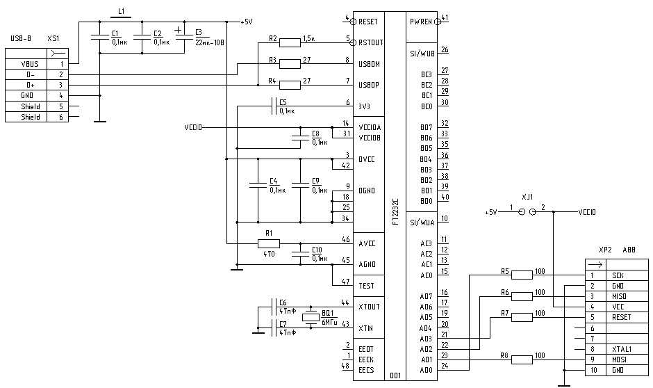
Only hardware MPSSE-based SPI supported now for FT2232, XTAL generation not allowed. See description of -a, -p switches and FT2232 configuration file for detailed explanations.
There are many FT2232-based adapters, mostly used for ARM-microcontrollers and all of them can be used for AVR programming.
Amontec JTAG key, JTAGkey-tiny
Olimex ARM-USB-OCD, ARM-USB-TINY
Turtelizer 2
ICEbear JTAG adapter
and many others. Some links can be found on
Hubert Hoegl's page
MegaJohn's design.
Sorry, russian only, but gerbers/pcad files/pdfs need no translations.
Use this config file for avreal 1.28r0 and higher.
enable=~adbus4,~acbus2
;adbus4 - buffers OE control, active low
;acbus2 - LED control, active low
Simplest adapter
Target board can be powered from USB +5V, install XJ1 jumper for this option. When the jumper not installed, FT2232 IO-buffers powered from target board and target VCC must be in 3..5V range.
For LPT adapters AVReAl uses software SPI implementation via different adapters. Some predefined adapters described below, almost any adapter can be defined by configuration file for LPT.
I recommend not use the simplest "5 wires" adapter. LPT chip distinctions and signal degradation can produce programming errors. Altera Byte Blaster useful also for Altera PLD programming (I'm never disconnect Altera Byte Blaster from LPT2 :-). Or make STK200/STK300 compatible adapter based on same bus driver with different wiring to LPT. Bus driver improve waveforms and allow to left programming cable be connected to board after program downloading. After programming AVReAl put bus driver outputs into high impedance state and microcontroller starts operation.
"FBPRG"
adapter
is simply wires that connect LPT connector pins with microcontroller ports as
shown in table
| LPT pin | AVR signal | LPT pin | AVR signal |
| 6 (D4) | /RESET | 8 (D6) | SCK |
| 7 (D5) | MOSI | 10 (ACK) | MISO |
| 5 (D3) | XTAL1 | 18..25 (GND) | GND |
Programming can be done both in target board powered from it's power supply and in small special board powered from parallel port (switch -ap) using all free LPT data outputs. But the last method can work incorrectly. Also You can program AVR chip without crystal (switch -o0) particularly if You want set up microcontroller to work with internal RC generator.
This adapter designed by Altera for it's PLD programming. I add Byte Blaster support to AVReAl because use Altera programmable logic and always keep this adapter connected to LPT.
Schematic shown below slightly modified:
1) LED indicators added (GREEN - power present, RED - programming in process).
2) Free bus driver output used for additional signal, passed to pin 8 of X2.
This line used for software XTAL1 generation (switch -o0).
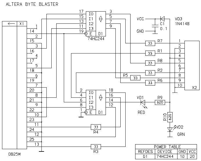
X2 connector pin assignments in AVR programming mode.
| X2 pin | AVR signal | X2 pin | AVR signal |
| 1 | SCK | 2 | GND |
| 3 | MISO | 4 | VCC |
| 5 | nRESET | 6 | Not connected |
| 7 | KEY | 8 | XTAL1 |
| 9 | MOSI | 10 | GND |
Use the same connection for ByteBlasterII. No adapter modifications required for XTAL generation
STK200 and STK300 are Atmel evaluation boards with At90s8515 and Atmega103 respectively. These boards supplied with programming adapter supported now by AVReAl according to requests of STK board owners. Schematic shown below has both autodetect wires - for STK200 (LPT pins 2-12) and STK300 (pins 3-11). Line 'LED' can be used for software XTAL1 generation (switch -o0).

Both "buffered" adapters use 74HC244 bus driver. I recommend use 1.5-1.8m length cable from LPT to adapter and 15-25cm cable from adapter to AVR microcontroller.
JTAG connector pin usage for AVR serial programming
| JTAG pin | AVR signal | JTAG pin | AVR signal |
| VCC (pin 1) | VCC | GND (pin 2) | GND |
| TCK (pin 4) | SCK | TDO (pin 6) | MISO |
| TDI (pin 7) | MOSI | TMS (pin 9) | nRESET |