| AVReAl | Description | Adapters | History |
Program compiled in following versions:
Win32 and Linux versions requires drivers/libraries for FT2232-based adapters support.
WIN32 version uses for LPT-adapters
| W95/W98 | - built-in module for direct port access |
| Windows NT4, Windows 2000, Windows XP 32 bit, Windows 7 32 bit | - driver DLportIO |
| Windows XP 64 bit, Windows 7 64 bit | - driver DLportIO x64 |
DLportIO - driver from DriverLINX package from Scientific Software Tools, Inc. (http://www.sstnet.com).
AVReAl designed for Atmel AVR microcontrollers programming in low-voltage ISP (in-circuit serial programming) mode. Supported adapters and adapter to microcontroller connections discussed in part "adapters").
In "fbprg-mode" all not used for programming process LPT data outputs can be used as "power supply" (switch -ap).
Programming without crystal also allowed, specified by switch -o0. This mode may be usable even if crystal exists for avoiding chip error "EEPROM not read by ISP for high crystal frequencies".
Input files - INTEL HEX. HEX-file loaded as list, not as array. As result "byte 0xFF in .hex" and "not mentioned byte" will retain as differ situations and only needed memory locations will be programmed and verified. Other locations can be verified for FF state by request (see switch -v+).
For all who like patch HEX-files manually: if checksum not match AVReAl ask
"ignore?” 'Y' (or 'y') forces to this an all other checksum errors will be
ignored (but checksum byte must be present in HEX file record).
For manual patches simplification (particularly for "formatted"
records in EEPROM) all white space characters removed from lines before analyze.
You can have HEX-file like this line
:08 0001 00 00 01 0203 0405 0 6 0 7 DB
All empty lines and lines started with '#' also ignored, you can put own comments directly into HEX-file.
Program check input file for records overlapping (can be produced by linker with erroneous command file).
avreal [switches] [[-c] code_file [[-d] data_file]]
or
avreal [switches] -d data_file (If you want write only to EEPROM)
File names without related switches (-w -r -v) ignored. More about switches -c, -d see below, after other switches description.
Switches
avreal +name -h('+name' must be before '-h') list of fuses supported for microcontroller 'name'
| -ie or -i1 | errors |
| -iw or -i2 | warnings |
| -i or -i3 | info (default) |
| -id or -i4 | debug |
| -it or -i5 | trace |
| -ip- | disable progress bar at all levels |
| -ip | auto, enabled at level "info" and above (default) |
| -ip+ | enable progress bar at all levels |
s=SERNO,d=DESCRIPTION
v=VID,p=PID
"-ps=FT01001A,p=6003"-pd="Dual RS232 A" | for FT2232C, FT2232L, FT2232D |
-pd="Dual RS232-HS A" | for FT2232H |
-pd="Quad RS232-HS A" | for FT4232H |
/dev/parport0/dev/ppi0
   -o3.686MHZ
   -o14745600hz
   -os1500
   -os3.8MHz
For backward compatibility the default units is kHz. If -o not specified the default frequency is 800 (0.8MHz)
-o0,8For STK adapters LED line used for XTAL generation. Altera ByteBlaster (ByteBlasterMV) must be slightly upgraded). ByteBlaster-II already has connection to header pin 8. Xilinx parallel download cable has no free line and -o0 can't be used.
avreal +chipname -?Keywords
_low, _high, _ext, _lock
used for bytename. You can specify fuses by byte basis.
_lock mark lock and BLB fuses byte but lock-bit positions
ignored, for chip lock operation switch -l must be used.fusename=val and bytename=val can be mixed, but
whole fuse byte must be specified either by bytename or
by fusename combination.
    allowed:     -f_low=C3,_high=F4,blb1=2
    not allowed: -f_lock=FB,blb1=2
Fuses writed or verified by using switches -W or -V
with switch -F.
Fuses not listed in -F remains unchanged except BLB group
for mega161, mega163, because of it can be erased by -E not depend
of -F existance.
BLB* bits behave as lock-bits. It is impossible to
write '1' (erase) to any programmed BLB bit without erasing all chip.
AVReAl display warning and end exit if such operation
requested.
Combinations of switches allowed:
-v -w      write, then verify
-e- -w -v  erase with EEPROM restoring, write, verify
-b -w      blank check, write IF BLANK
If two filenames exist without -C and -D
switches then 1st is file for flash code space, 2nd (if exist) for data EEPROM
space. If switches -C and -D used it mark files not depend if it
sequence. Spaces between switch and file name not required, you can use
-cfoo.hex or -c foo.hex.
If there are only one filename and neither -c nor -d
specified then this file contain information for code space (FLASH).
But if any records exist above top FLASH address for specified chip
than this information used for data space (EEPROM).
Example for 90s2313. If single HEX-file contain records
for addresses 0x800-0x87F then this bytes will be programmed to EEPROM
in range 0x00 to 0x7F.
Switches order doesn't care, operations always executed in order E B W V L. Programming aborted if blank check or verify fail.
Examples:
-e -b -w -v -l2
mean: erase, if blank then write, if verified then lock.
tiny12 -w -c foo.hex -c*osccal=1f3 -fcksel=3,boden=0Write file foo.hex into flash memory, write OSCCAL value at location 0x1F3 of flash memory, program fuse BODEN and set CKSEL group of fuses to state 0011 binary.
name offset extHEX-files must contain records for special parameters, avreal only override
default values in your program.
As special parameters can be used:
Internal RC-generator calibration byte
name
osccal with calibration byte number
(osccal0, osccal1, ...). For calibration byte 0 number can be omitted.
ext
-d*osccal3=3F2. Write 0 OSCCAL value decreased by 3 as part of LDI command.
   public osccal_ldi
   ...
osccal_ldi:
   ldi R16,0xFF
   out OSCCAL,R16
   ...
Find osccal_ldi value in MAP file produced by linker. Let it is equal to 0x120 (byte address, word 0x90). Execute command:
avreal +tiny12 -ewv -c foo.hex -c?osccal=120,-3
Device serail number
You can write sequential serial numbers in your devices.
name
serno with serial number length in bytes (1 to 4).
ext
-d*serno2=12,serno.txt2. Write 3-byte serial number as part of LDI commands. Number stored in file proj.serno
   public serno_load
   ...
serno_load:
   ldi R16,0xFF ; low byte
   ldi R17,0xFF ; middle byte
   ldi R18,0xFF ; high byte
Let
serno_load value form map-file is 0x120.
-c?serno3=120,proj.serno
name
bytes with data length.
ext
0xDEADBEEF at address 0x100 command must be
-c*bytes4=100,EFBEADDE
Channel A can be used for FT2232C,FT2232L,FT2232D and channels A and B can be used for FT2232H, FT4232H. Only hardware serial interface engine pins TDI (adbus1), TDO (adbus2) and TCK (adbus0) can be used as MOSI, MISO and SCK pins but inversion can be specifed.
By default TMS (adbus3) used as RESET, ENABLE not used.
PINMAP argument can be used for changing pin assignments.
Attention! Beginning from version 1.28r0 complete adapter signal set with '~' inversion control supported for FT2232-based adapters.
enable pin for FT2232-based adapters is processed in the same way as for LPT-based
so inversion mark '~' is required for buffers with active low enable input.
Serial number and/or description of used adapter can be designated in -p switch. Linux users must specify FT2232 VID and PID when them differ from default FTDI VID/PID.
Adapter can be configured by mapping interface signals to adapter pins.
PINMAP argument of swithes (-am and -aft2232) can be in one of two forms
=filename, for example
-am=bb2.cfg:configuration_string, for example
-aft2232:enable=~adbus4
Adapter name (parameter name) can be set by record
name = any string
Programmer signals (parameters mosi, miso, sck, reset, xtal)
can be set by records
signal_name = [~]pin_name
Inversion mark '~' denote that there are an inverter between known for avreal part of hardware (LPT connector or FT2232 chip pin) and contorller pin. Internal LPT port inversions handled by avreal and must not be marked in mapping file.
| FT2232 | adbus0..adbus7, acbus0..acbus3. |
| FT2232H | dbus0..dbus7, cbus0..cbus7 for both channels. |
| FT4232H | dbus0..dbus7 for both channels that supports MPSSE. |
| LPT | d0..d7 alf init strobe select ask busy error pe online.
Attention! Only d0..d7 LPT pins can be used for adapter outputs. |
key record defines pin that triggers programming when swuitch -k is used. Inversion mark '~' stands active low level.
Special pin groups set, power, enable, led_ok, led_error are used for programmer (adapter)
control. Comma-separated pin list can be used in these groups records.
For example, power pins for fbprg-like adapter can be described as
power=d0,d1,d2,d7 and STK200/STK300 bus driver enables
as enable=~d2,~d3.
Inversion mark before pin name denotes that this signal is active low.
Before programming start pins of group set are activated, led_ok, led_error are set in passive state. If power group isn't empty, it's pins are activated
with 0.3 second delay before next operation.
Then avreal makes pins of group enable active and starts programming.
After programming completion avreal acivates led_ok or led_error pins depending on operation result and deactivates enable group then power group.
Pins in set group stay active.
led_ok, led_error signals must be independent on enable otherwise they will be disabled.
-az should be used with FT2232-based adapters for proper status indication.
Configuration file searching order:
Configuration string contains records like configuration file records (excluding name) separated by ':' character. Trailing separator is allowed but is not mandatory.
Examples for Amontec JTAGkey configuration strings
Using TMS as RESET
-aft2232:enable=~adbus4Using SRST as RESET (second enable pin needed for SRST output enable)
-aft2232:reset=acbus1:enable=~adbus4,~acbus3
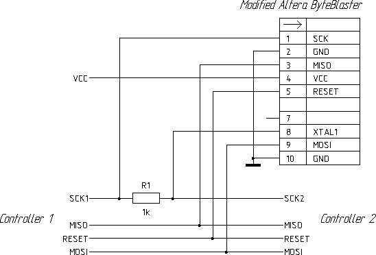
Example for system of two controllers connected together by SPI.
Let controllers connected as shown.
Controllers will free to communicate via SPI when adapter outputs are in hi-Z state.
For controller 1 programming use this mapping file:
name=1'st controller programmer
mosi=D6
miso=BUSY
sck = D0
reset = D1
enable=~ALF
set =~D3
For controller 2 programming use this mapping file:
name=2'nd controller programmer
mosi=D6
miso=BUSY
set = ~D0
reset = D1
enable=~ALF
sck = D3
AVReAl return completion status to operation system.